ID Manager (Detail Design)
The ID Manager enables you to associate Equipment IDs and Terminal Connection IDs with existing equipment objects. It also allows you to place new equipment objects into the current design file together with the selected equipment IDs. Existing Equipment IDs can be imported through the Excel import function or the iModel Import (Detail Design) function.
Difference between Equipment ID and Terminal Connection ID
Each piece of equipment can have multiple connections that are typically called terminal connections. Typically, a single cable is connected to each terminal connection. Cable Source and Target IDs are terminal connection IDs.
Terminal connections are not defined the same way an Equipment ID is defined. Terminal connections are established by importing a cable list that uses terminal connections as source and target IDs for cables.
In the following example, PMV1-X1 and PMV1-X2 are Source IDs for cables MV.PMV1.001 and MV.PMV1.002 and PMV1-X3 is target ID for cable MV.PMV1.003. The Source and Target IDs are the Terminal Connection ID's for the cable.

The ID Manager Interface
After requesting lock and reading, call up the advanced features in the ID Manager with the right mouse button.
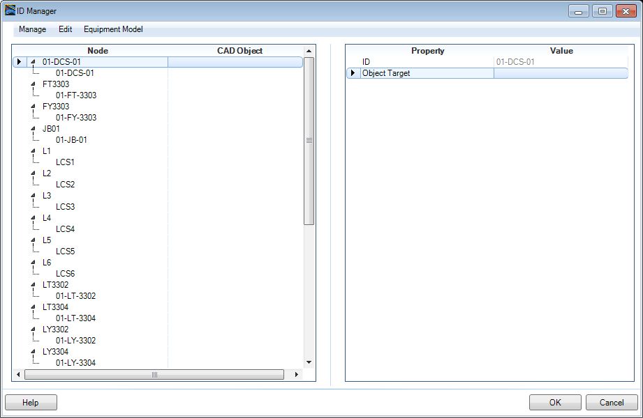
The ID Manager is setup with a Menu Bar at the top listing the available commands. Details on the menu commands are provided in the tables below. All of the commands can also be accessed via a context menu which displays when you right-click on an element in the manager. The options in the context menus vary depending on what element is selected.
Manage Menu
| Setting | Description |
|---|---|
| Collaborations Manager | Select this option to open the Collaboration Manager which enables you to check out design files and panels. |
| Import Equipment Map | Displays an Import dialog allowing you to import your Equipment.xls file along with the .xml map file. |
| Automatic Equipment Map | If the Equipment ID and Terminal connection ID are the same, you can automatically map them by selecting this option. This is equivalent to importing an equipment map, and saves time in that it automatically maps equipment and terminal connection IDs if they are the same. |
Edit Menu
| Setting | Description |
|---|---|
| Delete ID | Deletes the selected ID. |
| Rename ID | Displays the Rename Equipment ID dialog allowing you to specify a new name for the Equipment node. |
| Select all | Selects all objects in the ID tree. |
| Find | Displays the Find dialog, which enables you to locate a specific search string. |
| Filter | Displays the Filter dialog, which enables you to filter the values displayed in the Project Manager. |
| Set max view level | Reduce display (e.g. only on source). |
| Display Non-Associated IDs | It will only see the unmapped IDs, with this both options can be selected (Assigned or Unassigned). |
| Display Associated IDs | It will only see the associated IDs, with this both options can be selected (Assigned or Unassigned). |
Equipment Model Menu
| Setting | Description |
|---|---|
| Place Equipment | Select this option to begin the Equipment Placement procedure for the selected ID. The Equipment Manager will display prompting you to select an equipment component to define properties for, then you will be prompted to place the equipment in the design file using the standard placement procedure. |
| Add/Place Equipment | This option lets you add an equipment ID, then place
the equipment component using the Equipment Manager within the same procedure.
You will first be prompted with the
Add Equipment ID Dialog to create the ID. Once you have
completed that process, the
Equipment Manager displays so you can define the equipment
type and its properties to assign to the ID.
Once this is done, you then physically place the equipment into the design file. |
| Add Equipment ID | Displays the Add Equipment ID Dialog letting you define the type of ID to add. When you close out that dialog, the Panel Manager displays where you can define a Name for the new ID. |
| Add Terminal Connection ID | Click this option to add a Termination Connection to
the selected Equipment ID. The following dialog displays where you can define
the name of the connection ID:
Enter a Connection ID into the field and click OK. |
| Move IDs | Displays the Move IDs dialog letting you transfer a node ID from one node to another. |
| Associate ID/Equipment | When you select an Equipment ID and click this option, you will be prompted to select a equipment component in the drawing to associate with the Equipment ID. Once you have selected the equipment component, a unique Guid number for the equipment will display in the CAD Object column. This value will also display as the value for the Object Target field in the Properties section. |
| Disassociate ID/Equipment | This option will terminate the association between an Equipment ID and the actual equipment component in the drawing. |
| Find Equipment Without Cable Connections | Click this option to check if any equipment components in the drawing do not have cable connections defined for them. The Find Equipment without Cable Connections Dialog displays listing any equipment components from which you have the ability to either Delete the component, or Visualize the component in the drawing. |
| Update Design File | Updates the design file with the changes made in the ID Manager. |
| Visualize | Visualize the selected Connection in design file. |
| Zoom | Active Zoom function shows the selected Connection in design file only, inactive Zoom shows the Connection with last view settings. |
